 Supervisor with "VDS + FLB"
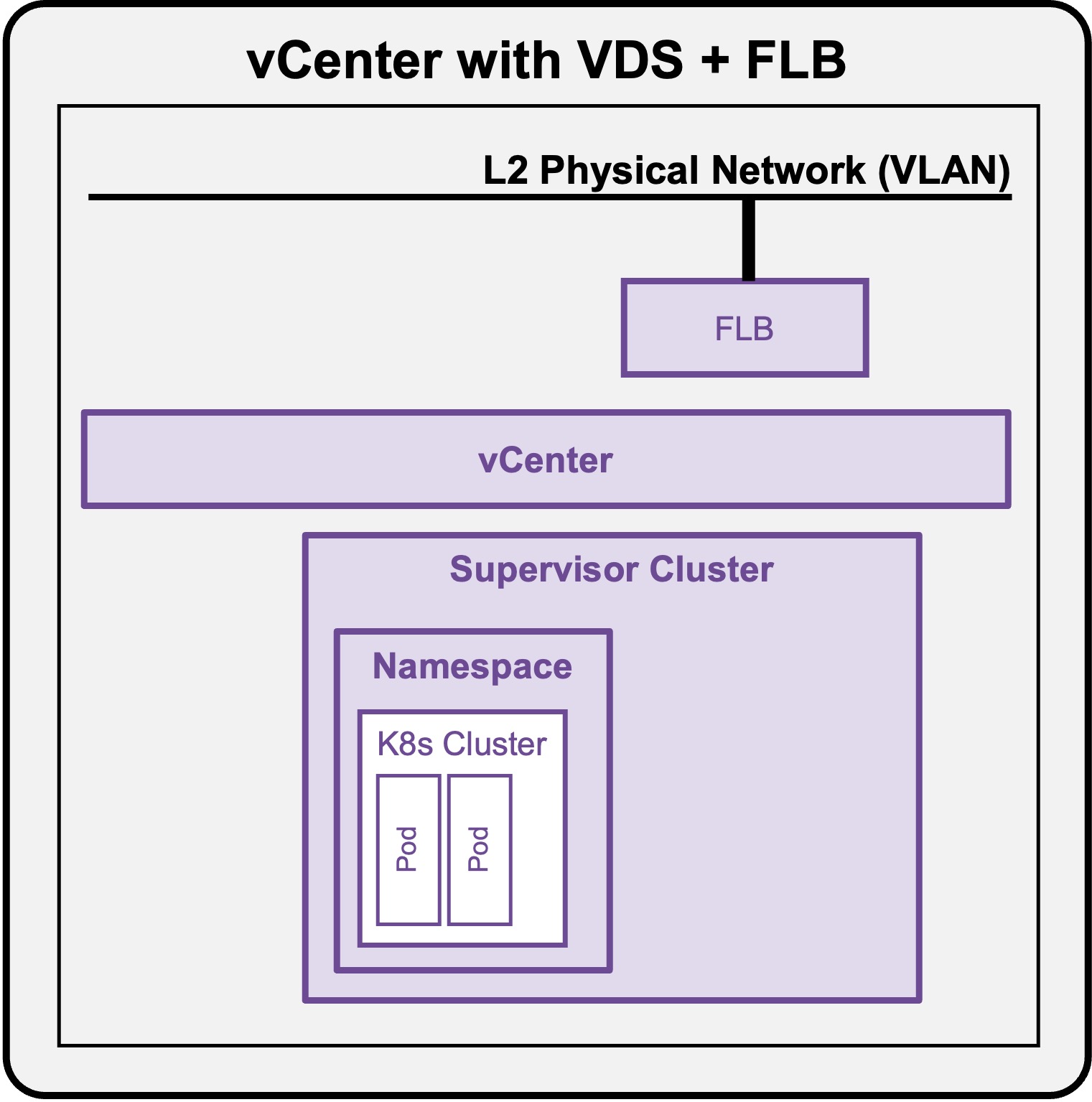
This section describes the procedures for Troubleshooting Network Services into the VKS Namespace utilizing a "VDS + FLB" architecture" inside a vSphere environment.
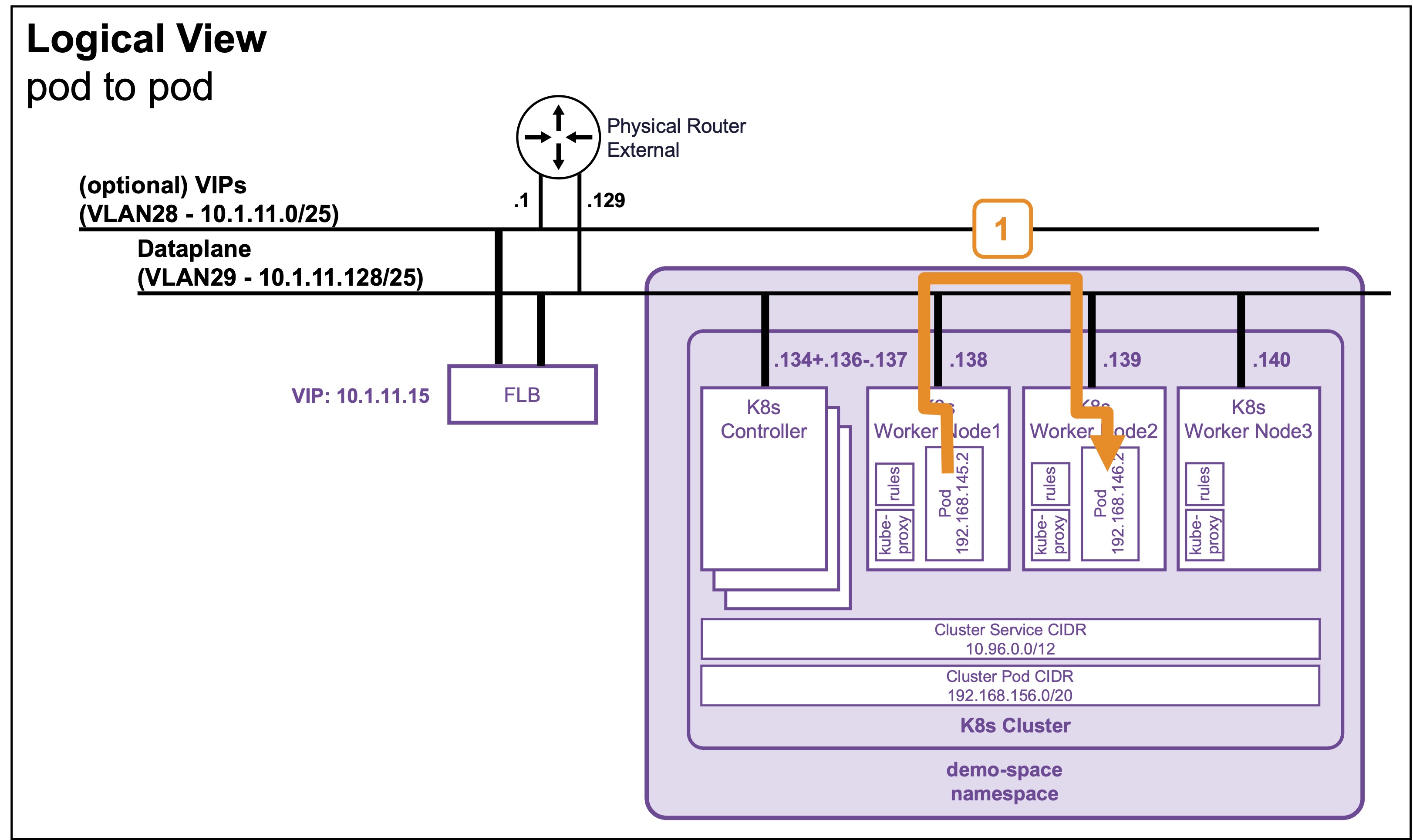
Packet Walk - E/W pod to pod
A Full Application (Load Balancer + Pods) has been deployed (see Application Deployment > App Deployment (K8s) > via CLI).
View
Logical View
Physical View
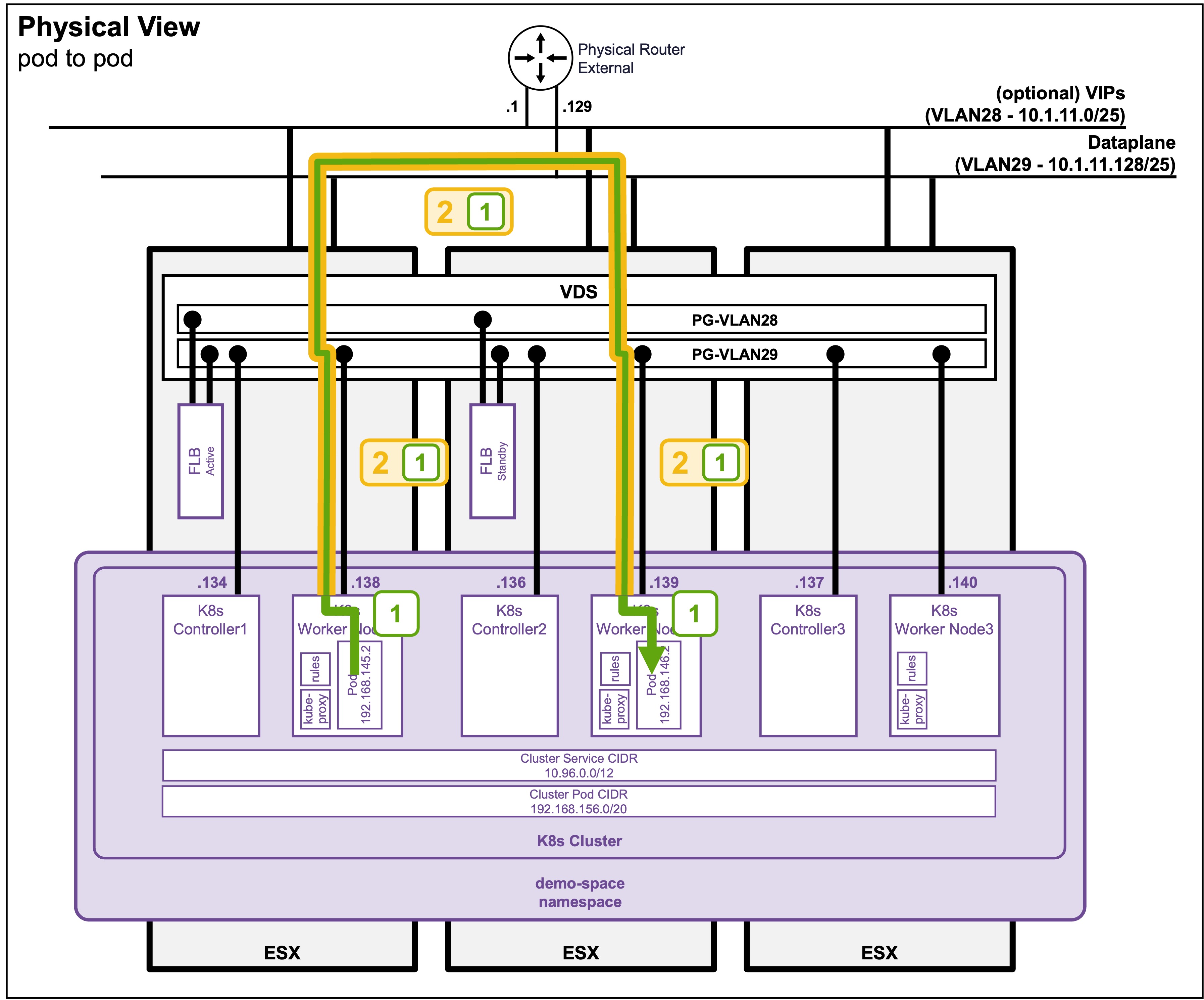
Packet Walk Explanation
-
Step 1: Traffic leaves the Source Pod
Source-Pod-IP (192.168.145.2) => Destination-Pod-IP (192.168.146.2)The traffic exits the source pod and hits the Worker Node's local routing engine (managed by
kube-proxyand the CNI agent, such as Antrea). -
Step 2: Cross-Node Encapsulation
WorkerNode1-IP (10.1.11.138) => WorkerNode2-IP (10.1.11.139)

  [Source-Pod-IP (192.168.145.2) => Destination-Pod-IP (192.168.146.2)]
The destination pod is on a different node, so the Worker Node encapsulates the original packet inside a node-to-node tunnel packet.
-
Step 3: Destination Node Decapsulation and Delivery (encapsulation2)
Source-Pod-IP (192.168.145.2) => Destination-Pod-IP (192.168.146.2)The destination Worker Node receives the node-to-node packet and strips away the encapsulation header. The local routing rules then deliver the unencapsulated packet directly into the destination Pod's network interface.